|
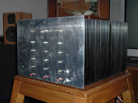
Another view (side view) of the heatsinks. Two heatsinks 202 mm each are joined together and this will house
two P3A boards at the sides. One can make out the wrongly drilled holes at the factory for the output transistors (this makes
the P3A boards go on the top side). The corrected holes have screws in them.
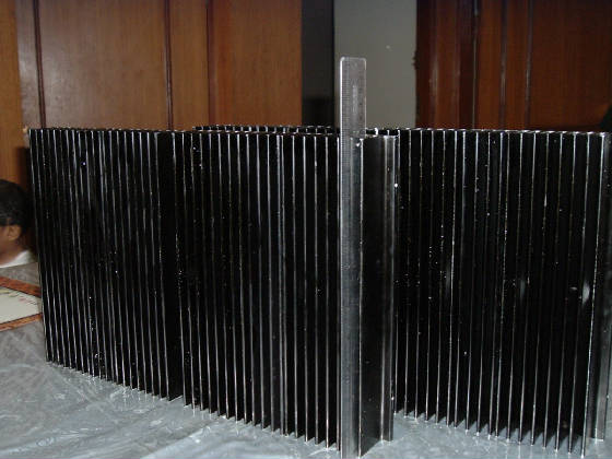
Just another view showing the height of the sinks.
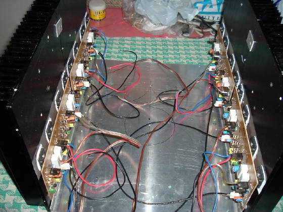
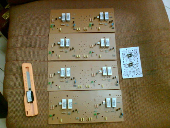
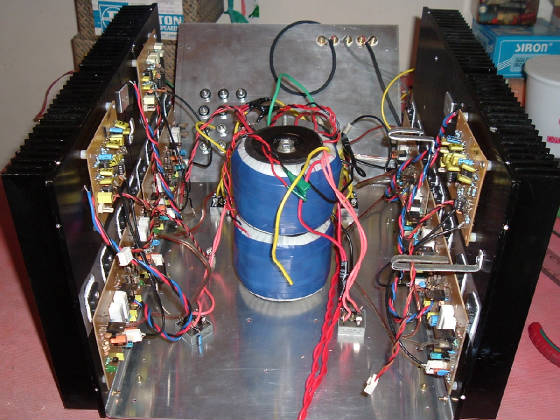
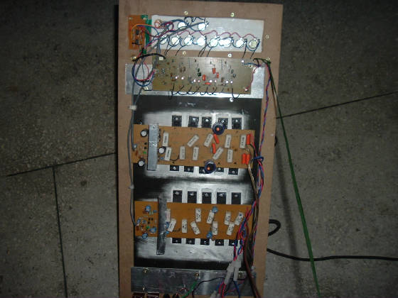
All the four P3A boards completed and mounted on the sinks. On the bottom of the case one can see the round
markings by black pen. This is where the Toroids will be place and the filter caps will come inbetween the toroids and the
power amps on both sides. I plan to place the P05 15-0-15 supply over the toroids.
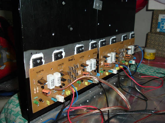
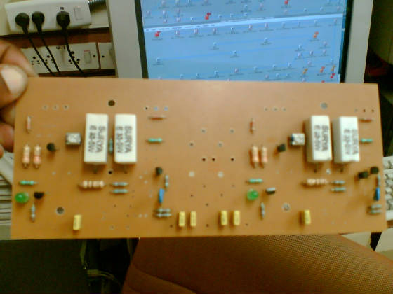
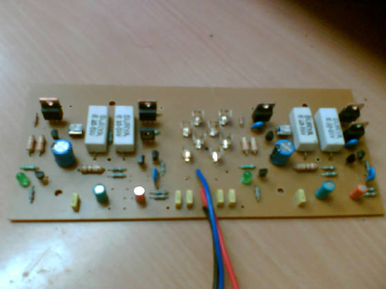
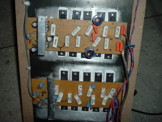
A closer look at the mounted boards. You can see that the inputs have removable connectors and it was a
pain to wire them as they already had wire in them which first had to be removed carefully (not damaging the pins) and soldering
sheiided cables to them. I powered two amps with 15-0-15 supply and played 50 hz tone through them but the sinks were at the
same ambient temp. after about 30 minutes. If one is observant, you can see the collector pin of the output transistors are
kept long. This is done to set the biasing current ( there is no space at the 5 watt collector resistors ! I also like
to see the thermal grease (paste) come out at the sides of the transistors while they are being screwed to the sinks.
Also mark the holes in the bottom of the case, along the sides for air ventilation.
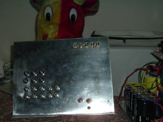
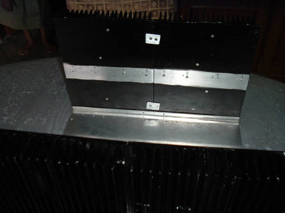
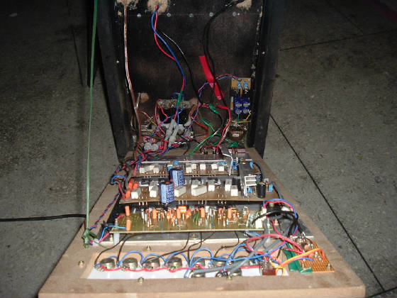
The back side from the inside. The input connectors (gold plated) and the speakers terminals have been
fixed and the two fuses for the mains are also fixed. The hole seen below is for the mains AC leed. The ground point is just
below this...on the base panel.
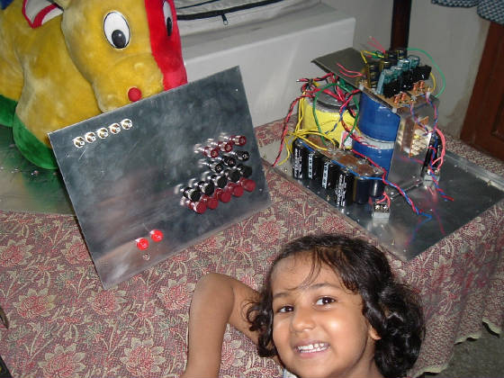
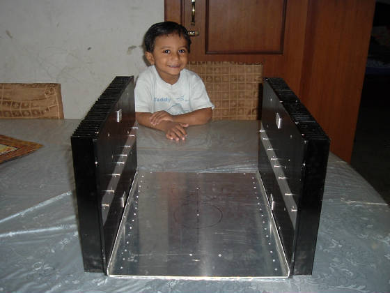
My eldest daughter wanted her photo with my system...
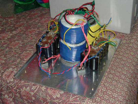
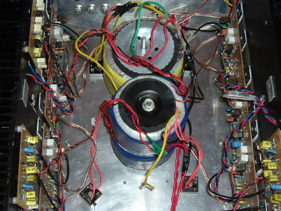
The back panel, outside view, and the 3 transformers...The one on the back (yellow) is 25-0-025, 580
VA with 15-0-15, 20 VA will supply AC to 2 rectifiers(one for the centre and one for the rear 2 channels) and the
15-0-15 will supply the P09 (centre ch.) & the two P97s (centre & rear channels). The two P05 can be seen
presently just kept over the transformer.
The other two transfromers (Blue, kept one over the other) is also 25-0-25, 300VA each with 15-0-15, 15VA
will power the front channels and the two P09s(Front left & front right) + the front P97 preamp. i.e. a total of 4, 35
amps rectifiers. The storage capacitors can also been seen where it will finally be placed. In total there is 2,00,000 uF...60,000
uF each front channels (30,000 per rail) and 20,000 uF each for centre and rear channels...an overkill I believe.
All the torriods are shielded and they are custom made.
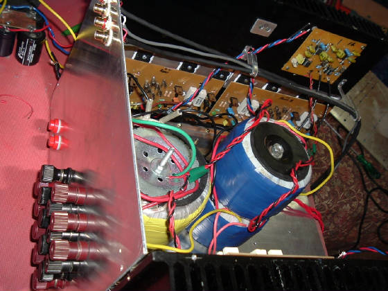
The plate over the torroids was made to gain space and the vertical part of this plate houses the DC bus
from the two P05s. This will help me in easy assembling of the system...an idea can change your Life!
The top torroid is just kept over the other as i was not able to find the required 7 inch bolt&nut for
fixing it ! One can also notice the copper plate in the supply storage pack which has gone dark brown...this was because i
cleaned it with an erasure !! After the cleaning it became wow, but now you can see it for yourself. (any suggestion how to
make it neat & clean?). The rectifiers is coated with thermal gerase for better conduction of heat. There are another
two of them at the back side of the caps. There are two STAR points and I plan two connect them together and the centre tap
of the yellow torroid will be connected to it at the centre of the wire connecting the two stars and from this point I will
be taking the grounding wire via a 10 ohm, 10 watt resistor.
Much work is required to be done during the 2 days I get "OFF" from the office. I will try to finally finish
the assembling part and "IF" the time permits...test the system.......I am afaraid to power it on !!!
UPDATED on 3rd Oct '05
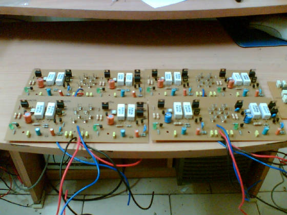
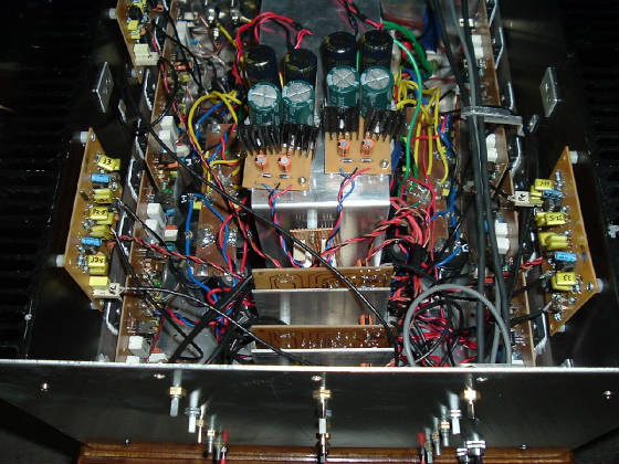
The above two pics shows the P3As & the P09s mounted on the heatsinks. I had planned to mount the LR
crossover in the front of the case, but as there was lots of space on the sinks, i placed it here to avoid congestion. Also,
it helps to identify easly the crossovers are for which amps. The transformers are now all mounted (after getting the right
size of the bolt!). As the base (and all) is only 2mm aluminum, I have mounted two steel strips below the case to hold
the weight of the transformers (they are real heavy!).
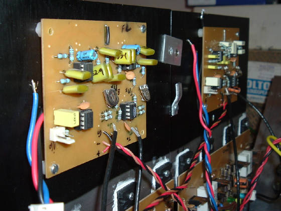
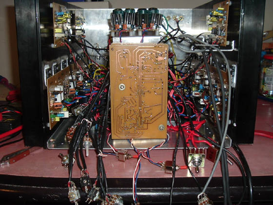
The LR crossover of their respective channls and view from the back.
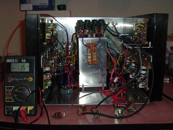
The one on the top (pic) shows the impedance between the 0 volt "STAR" point and the body(case).
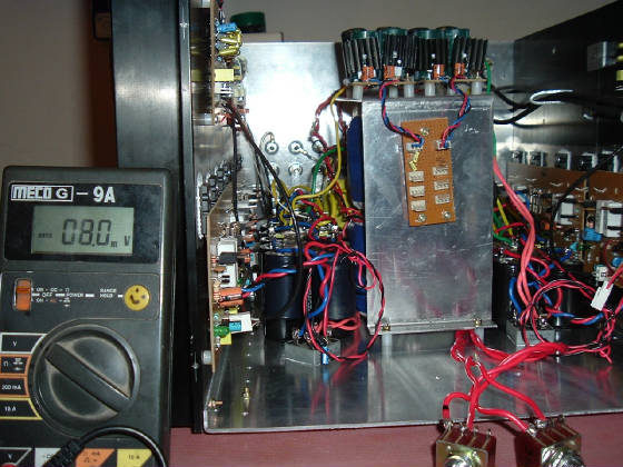
The second shows one of the outputs voltages with Iq at 90mA.
It may also be noted here that the storage capacitors have been mounted(stuck !) to the bottom case with
rubber adhasive(it holds for many, many years if not fiddled with).
The two P05s also mounted above the toroids and the connectors for the two bus bars of 15-0-15 v mounted
vertically.
The 3 preamps (P97s) installed. The wiring is in a mess...too many pots to fix.
After fixing the front pannel and the pots. Side and top views. Mark the hole (3) above the top pots for
LEDs. It may be worth stating here that all the holes (for pots, transformers, LEDs, etc, etc) have be drilled with a
hand driller.
Though there are a few places where the main AC IS crossing the signal lines, there is
"ABSOLUTELY" no HUM even at max. volume (in all the channels).
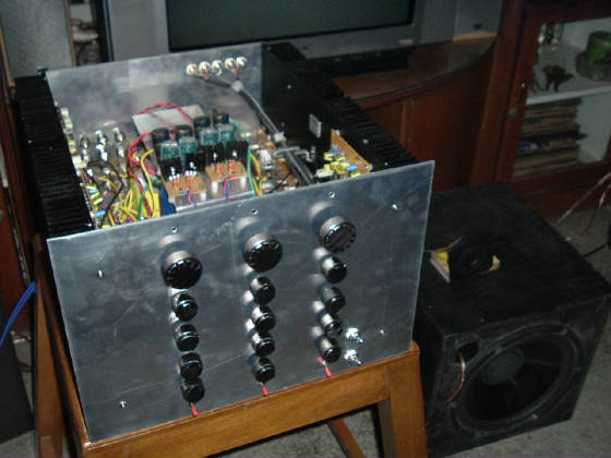
Top pic shows the pots mounted and a temporary centre speakers can be seen next to the amp on the floor.
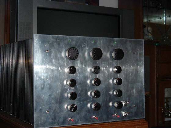
Front view of the MONSTER. The LEDs have also been installed (temp. arrangement as the front face has to
be anodized). Each LEDs shows it's section of the amp is ON or not(Front, Centre & Rear). The power for it has been take
from the AC of the bridge rectifier. and can be seen in the photos above. I have used 2.7k/0.5 w resistors for it (for 10mA).
There are two mains switches on the front right side and theses are used two switch ON the Front (upper
switch) and Centre&Rear channels(lower switch.)
Why I call it a monster?
The whole system is so heavy and if i have to move it, I move the table instead on which "IT"
is kept !!. But I have found the prefect place for it in my cabinet.
Hope "SAF" factor doesn't go out of the window...
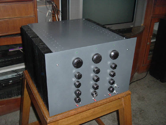
The Final look. The front and the top faces have been powder coated. I wanted the shade to be darker
(black with just a little shade of grey) but, the powder coating was done twice and the same was not achived. I did not want
to make another trip to this powder coating factory, so I left it as it was. It looks darker in reality, as the flash
of the camera has brightened it up further.
UPDATED 8th DECEMBER 2005
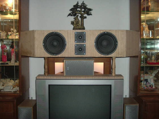
My HUGE Centre speakers which i was talking about. I have not yet filled it with Glasswool but it sounds
O.K.
The box is yet to be polished too.
MY SUBWOOFERs (470+250 Watts)
Here are some pictures of my subwoofer 2-in-1. It has both the versions of the P68 sub amps
with 8 band equilizer. I was not able to manage high power sub drivers here in India, so I have used car subwoofers as you
can see in the pics. each box volume is 46.6 liters (with transformers + storage caps fitted inside the box). I have used
1.33 ohms/ 5 watts resistors to get a total Qtc=0.71
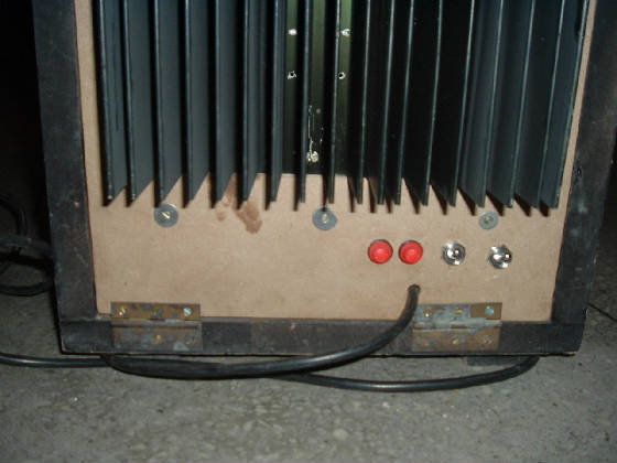
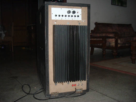
The back side of the sub box. The input is via a gold plated female RCA connector connected to the 8-band
sub equilizer. Acutally, the 8 band eqz. PCB is a cutout of the expandable graphic eqz. (24-band) I had made (one of
my 1st projects) and it can be seen that the OPamps are not there! Well, I was stupid enough to print the wrong side of the
PCB and developed it too!! Anyways, The Opamps are there- on the back (track side) of the PCB!
Then the 470 watts (top) with On-semis components and the 250 watts with Toshiba o/p transistors (below) P68s
can be seen on a masive heatsink. I do not need external cooling yet(presently it is nead cold here, but will see if it is
required in the summers). I am using line fused and can be seen in the pics.
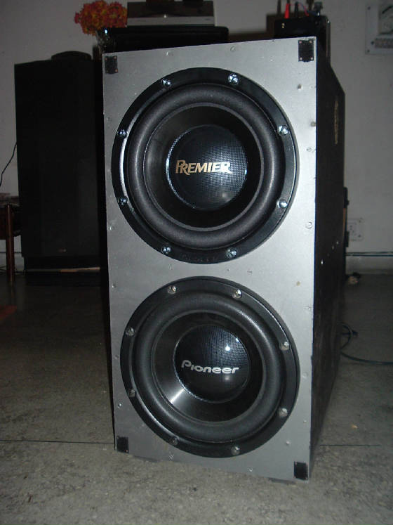
The car sub drivers. The top one is Pioneer's TS-125DVC (using only single coil) and connected to the 250
watts amp. The below sub driver is again Pioneer's TS-305C and is connected to the 470 watts amp.
The sub goes down to 18 hz when the whole room can be heard rattling but no sound from the sub, ansd there
is more than enough punch to make one's heart bear faster...well, the floors shake too! It would have been best to use proper
home drivers, but high wattage one are not avaliable here. What A SHAME.
I don't have any measurimg instruments, but the SPL is great.
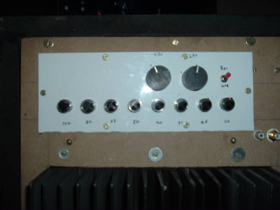
The Equilizer pots and the phase selection switch with the two volume controls.
And the two power switchs for each power amps with fuses. Most of the time only one is being used, and only
when my folks are away, I switch ON the other one too.

On top of the box you can see my hand held freq. generator (15 - 150 Khz). The sub (eqz.) was set using
this. The Equlizer has a max. gain of +/- 15db
THE WHOLE PROJECT IS AWESOME!
Cheers !
Rajeevk
E-mail: rajeevkgail@yahoo.com
|